If you are using an oscillating knife cutting machine and feel that it is very difficult to operate, then you can read this article several times, it will break down the operation steps of the oscillating knife cutting machine for you, and maybe it can help you. Because the author of this article has trained hundreds of users of oscillating knife cutting machines, and summed up a set of the simplest operation methods, which we call “433 Oscillating Knife Operation Method”, let’s start the process of this method explain.
Let’s first interpret the “433 Oscillating Knife Operation Method” as a whole, where “4” refers to the four elements of processing graphics, the first “3” refers to the three characteristics of the processing tool, and the second “3” Refers to the three points that need to be paid attention to before cutting.
So, let’s start with the four elements of processing graphics.
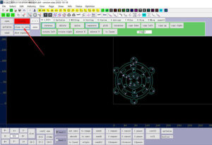
First, we can open the processing graphics in “DXF, PLT” format in the machine’s control software “Xiao”. Today, our explanation takes the gasket cutting industry as an example, so we input a gasket design graphic, we find the graphic to be input, and double-click it to open it in the software.

How to open processing graphics
We started optimizing for the first element of the machining graphics – setting the correct operation number. A variety of processing tools can be configured on the oscillating knife cutting machine – electric oscillating knife, pneumatic oscillating knife, bevel cutting tool, marking pen, indentation tool, etc., to meet the different processing needs of customers. Each cutting tool will have a corresponding operation number, and each operation number will have a corresponding color, for example: the operation number of the oscillating knife cutting tool is SP4, and the color is cyan. Which kind of cutting tool we want to choose for processing, we must choose the corresponding operation number, the method of setting the operation number is to change the color of the graph. For example: the color of the graph here is blue, and the corresponding operation number is SP5. If we want to switch it to SP4, we only need to select this graph, and then click the button of SP4.

setting the correct operation number
After we optimize the operation numbers of the graphics, we need to optimize the second element of processing graphics—the processing sequence.
How to view the processing order of graphics?
We click “View” and then click “Show Sequence” to get the processing sequence of the graphics. When we set the cutting order, we will adhere to a principle – first inside and then outside, from small to large, that is, first process the small internal graphics, and then process the outline of the graphics.
So, how do we set the processing order of graphics?
We can manually set the processing sequence of graphics. First, we will change the processing graphics into a closed graphics: click “Optimize”, and then click “merge linked”, then the processing graphics can be changed into a closed graphics. Then, we only need to click on the graphics, and then click the “sorting” button to set the processing number for each part of the processing graphics according to the principle of “first inside, then outside, from small to large”.

How to set the cutting order of graphics
Next, we set the third element of the graphics – the position and direction of the starting point. We can click “View” and then click “Show start” to display the processing starting point and direction of the graphics. We will find that some graphics processing directions are clockwise, and some are counterclockwise.
If we want to change all graphics to the same processing direction, how should we do it?
We click “Select”, then click “select anticlockwise”, at this time all graphics processed counterclockwise are selected, then we click the “Edit” button, and then click “Reverse”, so that the processing direction of all graphics becomes clockwise.
In addition to setting the same processing direction, we can also edit the position of the cutting location. For example, when the distance between the two cutting starting points is too close, we can click “Status” and then click “change start” to change the positions of all processing starting points are optimized.

How to optimize the starting point and direction of graphics processing
In this way, we have completed the attribute setting of the processing graphic operation number, processing sequence, and starting point position. After we have completed these, we can click the “close to axis” button to bring all the processing graphics close to the zero point coordinate position of the machine, that is, The last optimization setting we’re going to cover today. If the graphics are not close to the zero point coordinates, then we cannot accurately set the starting point of graphics cutting by setting the starting point of processing.
How to make the processing graphics close to the zero point coordinates
Finally, we can send the set cutting graphics to the machine for cutting and processing.
In addition to manually setting the four elements of the processing graphics, we can also use the optimization function that comes with the software to achieve automatic optimization. So how to do it?
We can reopen this processing graphic, then manually set its operation number, change it to the color we want, and then we click the “Config” button, and a dialog box will pop up, we can check the commonly used optimization options:
Check the “Clockwise” option, so that we have set the processing direction;
Then set the processing order to “Pieces order”, and all the graphics will be arranged according to the order of the final processing of the outline. We can choose a variety of sorting methods according to the processing requirements. The two commonly used sorting methods are “Pieces order” and “Sp order “;

automatic optimization
After we have set all the optimization options, we click “OK” to save. At this time, we only need to click the “optimize” button to complete all the optimization settings with one click.
The above is about the graphics optimization operation for oscillating knife cutting machine. In the next article, we will introduce how to set the three attributes of the processing tool.


